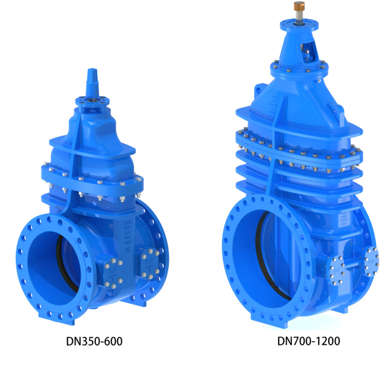
GATE VALVE, FLANGED, METAL SEATED, PN25
SS stem, gunmetal seat, galv. 8.8 bolts, CTC/CTO, blue FBE/2-pack

Contact
AVK Valves Company Hong Kong Ltd.
Unit 01-02, 21/F, Pilkem Commercial Centre, 8 Pilkem Street, Jordan, Kowloon Hong Kong
Metal seat gate valves with rotating, non-rising stem. Operating direction clockwise to close or clockwise to open. For drinking water and neutral liquids to max. 70°C, and sewage without solid impurities. On DN350-600 operation is either by manual handwheel/gearbox or by electric actuation; on DN≥700 operation is possible only via gearbox or actuator that is able to support the axial thrust loads.
AVK metal seated gate valves are designed for isolation of pipeline sections or individual pieces of equipment. The use of a ductile iron body and gate with bronze seal rings creates a heavy duty, watertight seal. The non-rising stem design ensures the stem thread is adequately lubricated by the water passing through the valve, a factor that safeguards the longevity of the valve.
| Variant 54/4142-002 | |
|---|---|
| Connection: | Flanged |
| Material: | Ductile iron |
| DN: | DN350 - DN1000 |
| PN: | PN 25 |
| Closing direction: | Clockwise to Close or Open |
Features
- Gunmetal bronze valve seat
- Metal faces machined to a high finish for optimum contact and minimum leakage
- Stem in stainless steel
- DN350-600 an NBR wiper ring protecting against impurities from outside; full circle brass thrust collar provides fixation of the stem and low free running torques; a replaceable polyamide bearing with two O-rings and independent O-ring stem seals
- DN≥700 stuffing box with ample depth gives long life to the PTFE packing
- Round body-bonnet O-cord gasket fixed in a recess to avoid blow-out
- Full bore
- Lifting holes for easy handling
- All rubber and coating in contact with the water are drinking water approved
- Guides on the wedge helps provide steady operation
- DN350-800 protected by 250µm blue fusion bonded epoxy coating
- DN≥900 protected by 250µm blue 2-pack epoxy coating
- Prepared for by-pass
Downloads
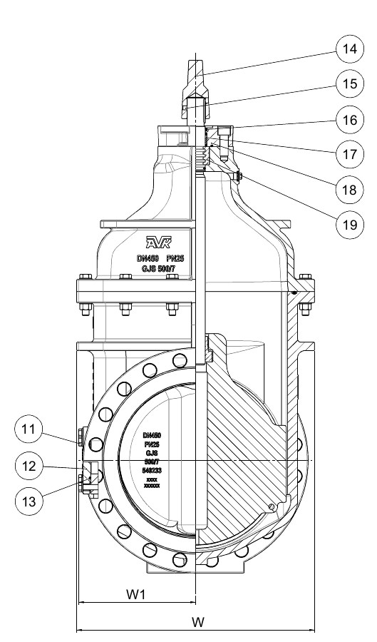
Reference nos. and dimensions:
| Reference no. | DN mm |
Operating Direction |
Flange drilling |
L mm |
H1 mm |
H2 mm |
W mm |
W1 mm |
F mm |
F1 mm |
F2 mm |
ISO flange |
Theoretical weight/kg |
|---|---|---|---|---|---|---|---|---|---|---|---|---|---|
| 54-0350-41-7141106 | 350 | CTC | PN25 | 572 | 834 | 278 | 598 | 278 | 40 | 48 | 189 | F14 | 398 |
| 54-0350-42-7141106 | 350 | CTO | PN25 | 572 | 834 | 278 | 598 | 278 | 40 | 48 | 189 | F14 | 398 |
| 54-0400-41-7141106 | 400 | CTC | PN25 | 610 | 910 | 310 | 658 | 298 | 40 | 48 | 189 | F14 | 524 |
| 54-0400-42-7141106 | 400 | CTO | PN25 | 610 | 910 | 310 | 658 | 298 | 40 | 48 | 189 | F14 | 524 |
| 54-0450-41-7141106 | 450 | CTC | PN25 | 660 | 995 | 335 | 708 | 348 | 40 | 48 | 194 | F14 | 653 |
| 54-0450-42-7141106 | 450 | CTO | PN25 | 660 | 995 | 335 | 708 | 348 | 40 | 48 | 194 | F14 | 653 |
| 54-0500-41-7141106 | 500 | CTC | PN25 | 711 | 1073 | 365 | 779 | 348 | 40 | 48 | 194 | F14 | 768 |
| 54-0500-41-7142106 | 500 | CTC | PN25 | 711 | 1073 | 365 | 779 | 348 | 40 | 48 | 194 | F16 | 768 |
| 54-0500-42-7141106 | 500 | CTO | PN25 | 711 | 1073 | 365 | 779 | 348 | 40 | 48 | 194 | F14 | 768 |
| 54-0600-41-7142106 | 600 | CTC | PN25 | 787 | 1240 | 423 | 904 | 408 | 40 | 48 | 194 | F16 | 1162 |
| 54-0600-42-7141106 | 600 | CTO | PN25 | 787 | 1240 | 423 | 904 | 408 | 40 | 48 | 194 | F14 | 1162 |
| 54-0600-42-7142106 | 600 | CTO | PN25 | 787 | 1240 | 423 | 904 | 408 | 40 | 48 | 194 | F16 | 1162 |
| 54-0700-41-7143106 | 700 | CTC | PN25 | 810 | 1749 | 513 | 1164 | 617 | - | - | 177 | F25 | 2147 |
| 54-0700-42-7143106 | 700 | CTO | PN25 | 810 | 1749 | 513 | 1164 | 617 | - | - | 177 | F25 | 2147 |
| 54-0800-41-7144106 | 800 | CTC | PN25 | 810 | 1900 | 563 | 1239 | 642 | - | - | 195 | F30 | 2501 |
| 54-0800-42-7144106 | 800 | CTO | PN25 | 810 | 1900 | 563 | 1239 | 642 | - | - | 195 | F30 | 2501 |
| 54-0900-41-7343106 | 900 | CTC | PN25 | 810 | 2118 | 613 | 1405 | 735 | - | - | 177 | F25 | 3811 |
| 54-0900-41-7344106 | 900 | CTC | PN25 | 810 | 2118 | 613 | 1405 | 735 | - | - | 191 | F30 | 3811 |
| 54-0900-42-7344106 | 900 | CTO | PN25 | 810 | 2118 | 613 | 1405 | 735 | - | - | 191 | F30 | 3811 |
| 54-1000-41-7344106 | 1000 | CTC | PN25 | 910 | 2273 | 680 | 1495 | 765 | - | - | 235 | F30 | 4371 |
| 54-1000-42-7344106 | 1000 | CTO | PN25 | 910 | 2273 | 680 | 1495 | 765 | - | - | 235 | F30 | 4371 |
Components
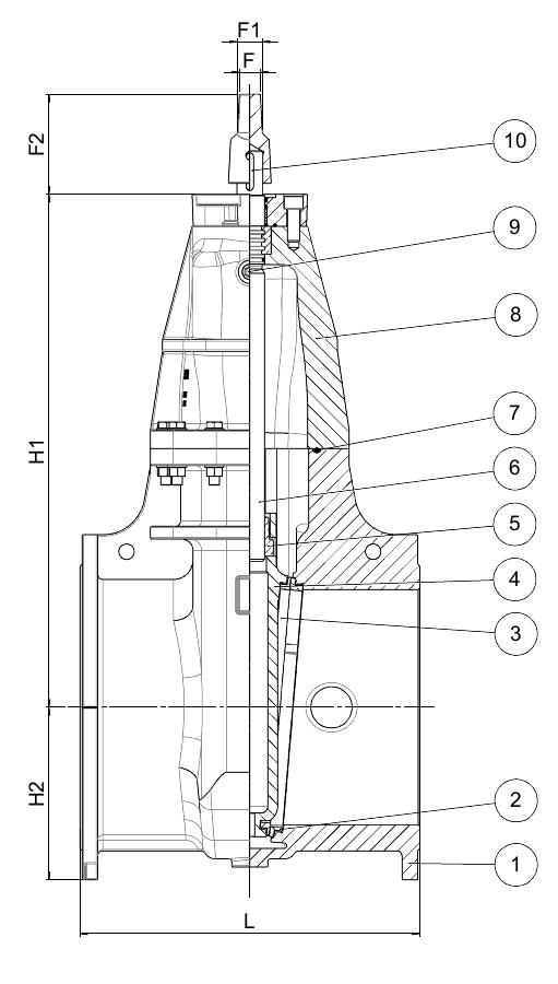
| 1. | Body | Ductile iron GJS-500-7 (GGG-50) |
| 2. | Seat ring | Bronze CC491K (LG2) |
| 3. | Face ring | Bronze CC491K (LG2) |
| 4. | Wedge | Ductile iron GJS-500-7 (GGG-50) |
| 5. | Wedge nut | Alu-bronze CC333G (AB2) |
| 6. | Stem | Stainless steel 1.4057 (AISI 431) |
| 7. | O-cord | EPDM rubber |
| 8. | Bonnet | Ductile iron GJS-500-7 (GGG-50) |
| 9. | Air plug | Stainless steel 1.4401 (AISI 316) |
| 10. | Key | Steel C45 (1.0503) |
| 11. | Bolts | Steel, hot dip galvanized |
| 12. | Blanking plate | Ductile iron GJS-500-7 (GGG-50) |
| 13. | O-ring | EPDM rubber |
| 14. | Stem cap | Grey iron |
| 15. | Screw | Stainless steel A2 |
| 16. | Wiper ring | NBR rubber |
| 17. | Bearing | Polyamide |
| 18. | Seal housing | Ductile iron GJS-500-7 (GGG-50) |
| 19. | Thrust collar | Alu-bronze CC331G (AB1) |
| 20. | Thrust nut | Alu-bronze CW307G |
| 21. | Distance piece | Ductile iron GJS-500-7 (GGG-50) |
| 22. | Gland | Ductile iron GJS-500-7 (GGG-50) |
| 23. | Packing | PTFE |
| 24. | Gasket | EPDM rubber |
| 25. | Stuffing box | Ductile iron GJS-500-7 (GGG-50) |
Test/Approvals
- Hydraulic test according to EN 1074-1 and -2 / EN 12266
Standards
- EN 1074 part 1 & 2
- Flange drilling to EN1092, PN25