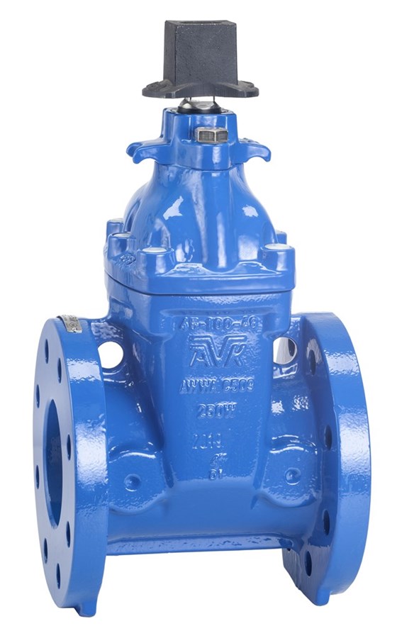
GATE VALVE,FLANGED, AWWA, PN10/16
SS/alu-bronze stem, wrench nut, EPDM (NBR gasket), A4 bolts, brass wedge nut, 250 µm blue EP, UL/ULC/FM

Contact
AVK Valves Company Hong Kong Ltd.
Unit 01-02, 21/F, Pilkem Commercial Centre, 8 Pilkem Street, Jordan, Kowloon Hong Kong
Flanged gate valve with wrench nut for fire protection applications to max. 70°C/160°F, rated working pressure DN 50-300: 250psi/17bar, DN 350-400: 200psi/14bar
AVK series 45 gate valves are designed to US-standards. Valve body, bonnet and wedge core are made of ductile iron which ensures high strength and reliability. The wedge is fully vulcanized with AVK's own drinking water approved EPDM rubber compound featuring an outstanding ability to regain its original shape. Corrosion protection is excellent with all iron parts coated with fusion bonded epoxy, fasteners in stainless steel and stem in either copper alloy or stainless steel.
| Variant 45/59-020 | |
|---|---|
| Connection: | Flanged |
| Material: | Ductile iron |
| DN: | DN50 - DN400 |
| PN: | AWWA C509 |
| Closing direction: | Clockwise to Close |
Features
- Integral wedge nut firmly fixed to the wedge prevents vibration
- Wedge fully vulcanized with EPDM rubber in a process that prevents creeping corrosion underneath the rubber
- Wedge sliding on guide rails gives smooth operation and low operating torque
- A large conical stem hole in the wedge ensures circulation and prevents stagnant water
- Stem of stainless steel AISI 304 with rolled threads (DN50-300) or high strength alu-bronze grade C63020 (DN350-400)
- Stem sealing with an NBR wiper ring, two upper O-rings in a polyamide bearing, one lower O-ring and one O-ring gland seal
- Round bonnet gasket fixed in a recess to prevent blow-out
- Bonnet bolts in A4 stainless steel, counterbored, sealed with hot-melt and encircled by the bonnet gasket
- Full bore and clear way
- Brass thrust bearing for low operating torque
- Fusion bonded epoxy coating blue RAL5017 in compliance with DIN 3476 part 1 and EN 14901
Downloads
Reference nos. and dimensions:
| Reference no. | DN mm |
Flange drilling |
L mm |
H mm |
H3 mm |
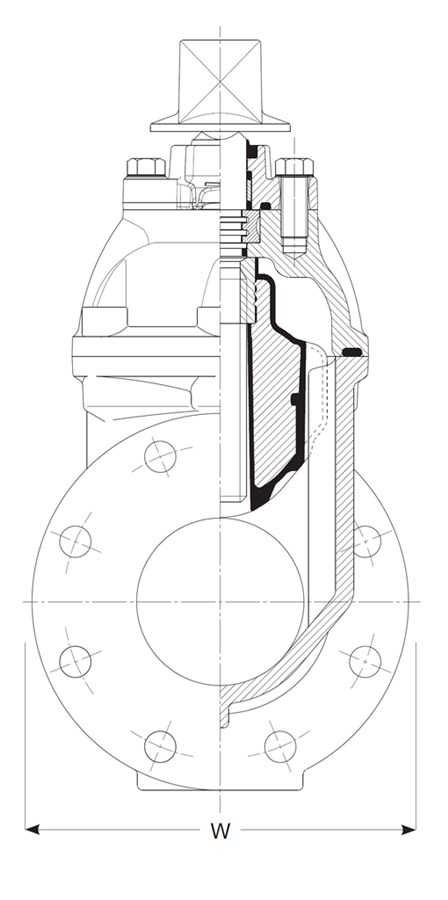
W mm |
Theoretical weight/kg |
Notes |
|---|---|---|---|---|---|---|---|---|
| 45-050-59-01614 | 50 | PN10/16 | 169 | 293 | 383 | 165 | 23 | Not UL listed |
| 45-250-59-016B4 | 250 | PN16 | 330 | 628 | 832 | 407 | 130 | |
| 45-300-59-006B4 | 300 | PN10 | 356 | 701 | 943 | 483 | 186 | |
| 45-300-59-016B4 | 300 | PN16 | 356 | 701 | 944 | 438 | 194 | |
| 45-350-5D-016B4 | 350 | PN16 | 381 | 891 | 1158 | 585 | 342 | |
| 45-400-5D-006B4 | 400 | PN10 | 406 | 893 | 1192 | 597 | 369 | |
| 45-400-5D-016B4 | 400 | PN16 | 406 | 893 | 1192 | 597 | 369 |
Components
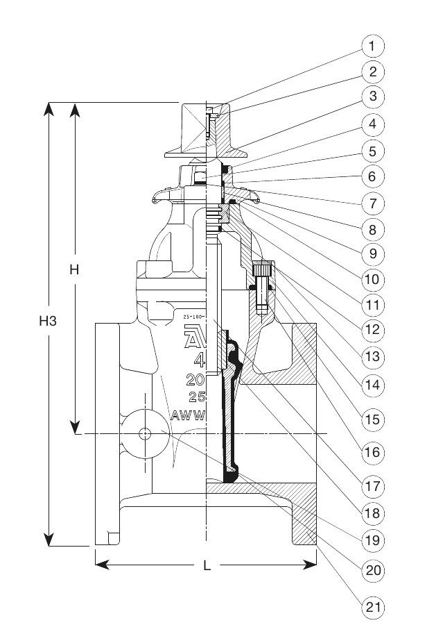
| 1. | Bolt, hexagon head | Stainless steel A4 |
| 2. | Washer | Stainless steel A4 |
| 3. | Wrench nut | Cast iron GJL-250 (GG-25) |
| 4. | Wiper ring | NBR rubber |
| 5. | Gland flange bolt | Stainless steel A4 |
| 6. | Stem seal O-ring | NBR rubber |
| 7. | Washer | Stainless steel A4 |
| 8. | Bushing | Polyamide |
| 9. | Gland flange | Ductile iron GJS-500-7 (GGG-50) |
| 10. | Gland flange O-ring | NBR rubber |
| 11. | Thrust collar | Brass DZR CW602N |
| 12. | Stem seal O-ring | EPDM rubber |
| 13. | Bonnet bolt seal | Hot melt glue |
| 14. | Bonnet | Ductile iron GJS-500-7 (GGG-50) |
| 15. | Bonnet gasket | NBR rubber |
| 16. | Bonnet bolt | Stainless steel A4 |
| 17. | Stem | Stainless steel A2 |
| 18. | Wedge nut | Brass DZR CW602N |
| 19. | Boss | Ductile iron GJS-500-7 (GGG-50) |
| 20. | Wedge | Ductile iron GJS-500-7 (GGG-50) |
| 21. | Body | Ductile iron GJS-500-7 (GGG-50) |
Test/Approvals
- Seat: 1.5 x PN (in Bar). Body: 2 x PN (in Bar). Closing torque test.
- UL listed/FM approved
Standards
- AWWA C509, FM 1120/1130, UL 262
- Face-to-face dimension according to ANSI B16.10
- Flange drilling to EN1092, PN10/16